Annual preventive maintenance
One full PM visit per year, on-site or remote depending on your facility. Detector calibration verification, full background survey, isotope library refresh, and clean COC documentation for your inspector.
Common-issue troubleshooting, repair videos, maintenance schedules, and a one-form path to register your instrument or open a service ticket — all in one place.
Most service tickets we receive turn out to be one of the items below. Walk through these first; if your instrument still isn't behaving, the next step is a 5-minute call to our service desk.
It’s an LTI design principle: no carousel, no automated sample changer, no mechanical advancement, no moving parts. Your Multi-Wiper counts every well simultaneously. Your Wiper Gold counts one sample at a time, loaded by hand. Nothing rotates, nothing slides, nothing wears out mechanically.
That’s why this troubleshooting list is brief: most service issues on LTI instruments come down to sample handling, well contamination, or a calibration alignment — and most of those are resolved in a 5-minute phone call before any disassembly happens. The articles below are the most common patterns; if your situation isn’t here, the next step is the service desk.
This is the most common service call we get. Auto Gain Adjust just finished cleanly — gain in range, all wells passed, the printout looks great. The next Efficiency Check on the Cs-137 (or Co-57) source returns DPM Invalid. Nothing’s broken. There’s one procedural step the menu structure doesn’t make obvious.
What’s happening. Auto Gain Adjust changes the detector’s electrical response, so any previously-stored efficiency value is no longer valid. The firmware protects you by resetting every stored measured efficiency to 100% as a placeholder — not a measurement, a flag meaning “not measured since recalibration.” Efficiency Check sees that 100% and refuses to compute a fictional DPM. It prints DPM Invalid rather than lie to you.
The fix. Before running Efficiency Check, run Measure Efficiency for each isotope you’ll be counting. It does NOT live under the Calibration menu — it lives inside the edit screen of the Isotope Library. Open the isotope’s edit page, enter the source’s reference activity and reference date, then select Measure Efficiency. Once that’s populated, Efficiency Check works the way it’s supposed to. The same procedure applies to the Multi-Wiper, Wiper Gold, Genesys Genii, Genii HE, and Gamma 1 — same firmware family, same flow on every counter.
Step 1: Power cycle. Always. More than half the time, this is an ADC that’s locked up — and a clean power cycle clears it. This is the universal first step for any lockup on an LTI instrument: counts, display, anything that isn’t responding the way it should.
If a power cycle didn’t fix it, narrow the symptom:
Step 2: Sample handling.
Step 3: Run the automatic calibration. If the check source itself reads low or zero, run the auto-calibration routine on the instrument. That fixes roughly 90% of remaining low-count issues by re-aligning the detector to its calibrated baseline.
Still off after all three steps? Call us. Most remaining issues are resolved over the phone in a few minutes. Please don’t open the instrument before calling.
If your DPM looks higher than you expected, the most common reason is that full Spectrum Compensation was applied — and the number you’re seeing is actually correct. Spectrum Compensation is a two-step correction:
With both corrections active, the displayed DPM can be significantly higher than what raw counts would suggest. That’s the system doing its job — both the detector efficiency and the gamma yield of the isotope are being accounted for. If you compare a fully-compensated DPM to your mental model based on raw cps, the numbers will look surprising.
Things worth checking before you assume something’s wrong:
What you don’t have to worry about: The compensation curve for your well configuration (Standard, LSV, 2″×2″) is baked into firmware per hardware. You can’t accidentally apply the wrong curve — the instrument knows its own configuration.
A note on calibration source choice — why we use Cs-137. NaI(Tl) crystals have a known non-linearity in the 100–200 keV region. Calibrating with cobalt pegs the cobalt photopeak exactly where it should be and works well for lower-energy isotopes like Tc-99m and I-125 — but the crystal’s non-linearity introduces a small shift at higher energies. The Wiper Gold factory calibration uses Cesium-137 because the Cs-137 decay produces two well-separated peaks — the 32 keV X-ray from the Ba-137m daughter at the low end and the 662 keV gamma at the high end. Using both peaks together, the 4096-channel MCA actively stretches and compresses the spectrum (zero-offset adjustment) until both peaks land exactly where they should. Some keV ranges end up with two channels per keV, others with five — whatever the linearity correction needs.
That’s the engineering reason we put a true 4096-channel MCA into the Wiper Gold: we only display up to 1000 keV, but having ∼4× the channels gives us room to per-keV-correct linearity in software. As far as we know, no other counter in this class does it that way.
If the DPM is genuinely off after that — off from a known check source by a real margin, not just “higher than I expected” — that’s a calibration alignment. Power cycle first (see the article above); if it persists, call us.
What the 2″×2″ configuration is actually for. The HE uses larger NaI(Tl) crystals to provide additional crystal mass for stopping mid-range gammas. The standard detector counts cleanly up to 1 MeV, but efficiency drops into the single digits past roughly the halfway point of that spectrum — so on a low-activity sample in the 300–800 keV range, a standard configuration can miss real counts. The extra mass of the 2″×2″ fills that gap. One real-world example: pediatric Chromium-51 (320 keV) studies, where samples are intentionally small and every count matters. Above roughly 800 keV the additional crystal on the sides doesn’t help much — those gammas blow through both configurations — so the HE’s cost-to-benefit drops off at the very top of the energy range.
Where the 2″×2″ actually loses to the Standard configuration. Below the midrange — cobalt-57 and lower — the HE is the worse choice, for two real physical reasons:
So the HE has a real energy sweet spot: the 300–800 keV midrange. It’s worse at the bottom (low-energy absorption losses), better through the middle, and only marginally better at the top (gammas blow through both). If you’re counting I-125, Tc-99m, or other lower-energy isotopes, the Standard configuration is the right tool. The HE is engineered for the midrange specifically — it’s not a general-purpose upgrade.
A note for buyers comparing counters. Some competitors fit every well with a 2″×2″ NaI(Tl) crystal because, on a spec sheet, “bigger crystal” sounds better than “right-sized crystal.” Physics doesn’t always agree. The same crystal that helps in the midrange actually hurts at the low end — through the two real physical mechanisms above — and a glossy spec sheet won’t show you that. If you’re evaluating a counter and the data lists a 2″×2″ as the only available geometry, ask the vendor for measured efficiency at I-125 (or whichever low-energy isotopes you actually count). A hedged or unavailable answer is the answer.
Sizing the crystal to the energy range is the kind of decision you make when you’ve actually done the physics — not when you’ve optimized the bill of materials. We maintain two configurations because we’d rather solve the engineering problem than make the spec sheet look impressive. The cost of doing it right is ours; the benefit is yours.
At HE-level sensitivity, ambient background and slight well contamination matter more than they would on a Standard configuration.
If background drifts up over weeks with no environmental change, call us — we’ll review the trend with you.
Some daily variation is normal — and expected. Backgrounds shift day to day for real reasons, which is why we ask every operator to run a fresh background every 24 hours rather than trusting yesterday’s reading.
One reframe that’s worth understanding. Our gamma counters are wrapped in lead not because they’re emitting anything — they aren’t — but because the world around them is faintly radioactive in a thousand small ways. We’re trying to count samples at very low activity levels, so the instrument has to be shielded from naturally-occurring environmental gammas just to give you a clean measurement. That’s a real distinction worth making the next time someone says “you work with radiation, that’s scary” — the lead is there to protect the measurement from the world, not the world from the instrument.
What can shift a background:
The diagnostic question to answer: is the elevation internal (contamination) or external (interference)? One straightforward test isolates this:
Still elevated after all three steps? Call us. At that point it’s likely a genuine internal issue — a marginal amplifier, a noisy preamp stage, something in the electronics that needs a hand on the bench. Those are rare on LTI counters — there are no moving parts to wear out, so when something does drift, it’s usually electronic and usually fixable from the inside — but they happen, and that’s when a phone call is the right next step. We’ll review the trend with you against your install-time baseline before anyone touches anything.
What the inside of an LTI well actually is. The well is shielded by lead (metal, not glass), and the surfaces you actually touch with a wipe are thin aluminum and stainless steel. The aluminum is intentionally thin to maximize detector geometry — which means anything that attacks aluminum will damage your well very quickly. This is the constraint every decontamination chemistry has to satisfy on LTI counters.
What we recommend: S4FE-D™ spray and wipes are the only decontaminants we recommend for use inside the well or on the detector face. The chemistry is essentially pH-neutral (~6.5), non-corrosive on aluminum and anodized surfaces, and was engineered originally because nuclear medicine technologists were destroying LTI gamma-counter detectors trying to clean I-131 with whatever was under the sink.
What to avoid in or around the well:
What “made for radioactive decontamination” doesn’t guarantee.
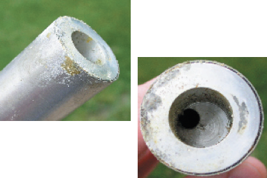
The photograph below is an LTI detector well that was cleaned with another brand’s commercially-sold radioactive decontamination product — not a household cleaner, not an industrial acid, but a chemistry specifically marketed for cleaning up radioactive contamination. The chemistry dissolved the aluminum, ate into the underlying NaI(Tl) crystal, and left visible crystallized residue around a hole through the well floor. The instrument was a total loss.
“Radioactive decon” is not an industry-standard formulation. Different products from different vendors use very different chemistries, and several of them are aggressive enough to do this on contact with the thin aluminum surfaces of an LTI well. The only decontaminant we test, certify, and recommend on LTI counter wells is S4FE-D™. If someone offers you a different product and tells you it’s “just as good,” ask them to put that in writing alongside their replacement-detector warranty.
This isn’t hypothetical. The instrument pictured below was reported to us by the customer as a fairly new unit with a deadlock problem, and they filed it as a warranty service claim. When the counter arrived at our facility, the chemistry damage you’re looking at is what we found inside — not a manufacturing defect, not normal wear. The warranty did not cover it, and replacing the detector became a costly lesson on which decontaminant the lab uses on the inside of an LTI well.
Note: S4FE-D is also safe on lead glass — useful for cleaning syringe shields, L-blocks, and other shielded glassware around the hot lab — but LTI counter wells don’t contain lead glass, so that’s not the constraint here.
For ground-in contamination, the 16 oz S4FE-D™ Concentrate diluted 1:10 with distilled water makes ~175 oz of working solution. See the S4FE-D page for the full product line.
Detector Well Liners. The liner stays in the well full-time. You do not run a sample in a bare well. There are two reasons for that, and both of them protect the most expensive part of the instrument:
Keep extras on the shelf. The right way to run liners is rotational: when one gets dirty or contaminated, pull it, drop a fresh one in, and clean the dirty one with S4FE-D in a fume hood. Having an extra set on hand means you never lose count time waiting on a liner to dry. Liners are cheap; detectors are not.
Note on attenuation: a liner does attenuate slightly, but because it is in place during normal operation — including when your calibration check sources are counted — the attenuation is baked into your standard curve. It is a fixed condition, not a variable. There is no scenario on an LTI well counter where you should be running “liner-out.”
Sample Tube Trays and Carriers. These are the batch-workflow accessories. Carriers go into trays; trays drop into the Multi-Wiper.
Where trays really earn their keep: RIA. The classic use case is a high-throughput RIA workflow where you stage tray 2, 3, 4 (and beyond) while tray 1 is counting, then swap them through continuously. If that’s your shift, having a stack of trays on the bench and treating carriers as a consumable line item is the correct setup.
Where you can skip the tray stack. Single-well counter work, or typical clinical wipe-test work on a Multi-Wiper, usually doesn’t involve more than a tray or two per session. You don’t need ten trays sitting on the shelf for that workflow — one or two is plenty.
All four accessories — well liners, sample tube trays, sample tube carriers, and counter-printer paper — are on the Products page under Accessories. In-stock consumable orders typically ship within 24 hours (often same day if the order lands before our cutoff — we ship from Central Time, so West Coast orders that come in mid-afternoon will usually go out the next business morning). Call or email if you need an ETA on a specific item before you order.
The short answer: if you have a Genesys 5000 or an OTC 7000, both remain on our active service list. We will keep it running.
One model, two badges. The OTC 7000 is the Genesys 5000 in its Organon Technica private-label configuration — beige paint, OTC sticker on the front, the on-screen company label changed from "Laboratory Technologies" to "OTC." Identical hardware, identical firmware, identical service path. Everyone in the industry knew about the arrangement at the time, but if you’ve inherited an OTC-badged unit and weren’t sure what was inside, that’s the answer. Same instrument; we support both names on identical terms.

All parts are available — refurbished. We no longer manufacture new components for these generations, but our refurbished-parts pool covers everything that fails: detectors, PMTs, amplifiers, power supplies, computer boards, front-panel controls, cabling, the works. If something on your instrument breaks, we can repair or replace it.
The CRT display question. Original 5000 and 7000 displays were CRTs, and CRTs are no longer produced anywhere in any quantity worth tracking. We have a direct LCD replacement that drops into the original panel cutout and runs off the same signal — so a dying or dead CRT is not the end of your instrument. The conversion is a service-bench job at LTI.
Realistic turnaround times (this is the part where we won’t over-promise):
If demand picks up, we’ll stock more. The honest answer right now is: low stock, all sourceable. If this website starts driving steady traffic from labs that want to bring older 5000s and 7000s back into service, we’ll start holding inventory on the higher-runner parts — including the LCD. Today, we don’t, because the call volume hasn’t justified it.
No migration pressure. We don’t push customers off legacy units. You bought it, you own it — and if you’re still getting good clinical or research data out of a 5000 or a 7000, the right answer is to keep running it. If and when you decide to look at a replacement on your own timeline, we’re happy to talk about the current Multi-Wiper, Wiper Gold, or Genesys Genii / Gamma 1 lines. But that’s a separate conversation from “my 5000 needs a board.”
How to start a service request: Use the service form below. Pick the matching legacy option from the instrument dropdown, describe what’s failing, and we’ll be in touch within one business day to scope the repair and confirm parts ETA before you ship anything.
The short answer first. LTI does not ship radioactive sources with our instruments. NRC source-handling licensing was not worth maintaining for our volume, so we let our license lapse. You buy the counter from us; if you need a purchased source, you buy it from a licensed source supplier. Below is where to look.
You may not need to buy a source at all. All current LTI gamma counters — Multi-Wiper, Wiper Gold, Genesys Genii, and Gamma 1 — support an I-125 self-calibration procedure that uses a small aliquot of a clinical patient dose in place of a purchased calibration standard. If you have access to I-125 capsules or solution as part of your clinical workflow, you already have a usable check source on the bench. The walk-through is here:
For most clinical and nuclear-pharmacy customers, this is the right answer and you can stop reading.
When you do need to buy a source, here’s who we recommend:
When you order, ask for 0.5 µCi (18.5 kBq) — not 0.1 µCi. A 0.1 µCi Cs-137 source is right on the edge of usable from day one. Cs-137 has a ~30-year half-life, so even though decay is slow, a decade in the source has dropped to roughly 80% of its original activity — and a marginal source becomes more marginal. 0.5 µCi has the headroom to stay a confident, statistically clean check source for the working life of the instrument, no swap required. Same vendor selection — just spec the activity right the first time.
A deliberately short word on RSO paperwork. The federal framework (NRC, 10 CFR Part 35 and related) covers part of the source-swap procedure, but a substantial portion is regulated at the state level, and state regulations vary. We’re not in a position to give a one-size-fits-all RSO procedure that would actually apply to your facility, your license, and your state. That conversation belongs with your RSO and your state radiation control program — they know what your license permits, what records you have to keep, and the time windows they hold you to. We’re happy to help on the instrument side; we don’t pretend to be your compliance department.
Swapping in a new source on the instrument — it’s simpler than people think. The full procedure is in your operator manual, but the short version is this: all source bookkeeping happens through the Edit screen of the ISO (Isotope) Library. There’s no service-mode menu, no calibration password, no factory dance. You enter three pieces of data:
Save the entry, then run an efficiency count on the new source to refresh that isotope’s efficiency factor in the instrument. That’s the whole procedure. The exact menu path varies a little between Multi-Wiper, Wiper Gold, Genesys Genii, and Gamma 1, but the three fields and the efficiency run are the same on all of them — check your operator manual for the button presses on your specific instrument.
How often does this come up?
If you get stuck on the firmware procedure or the efficiency count looks wrong after a swap, then call — but for the routine I-125 or Co-57 swap, the manual covers it and most operators are done in a few minutes.
Total keypad failure on a Wiper is almost never the keypad itself. The keys feed into a CPLD on the main board through a 16-pin matrix — for every key to fail at once, all 8 signal lines (4 rows + 4 columns) would have to fail simultaneously, which isn’t how electronic failure works. The cause is upstream of the keys: the keypad ribbon cable has come partly disconnected at the main-board connector.
How this happens: the Wiper’s LCD and keypad sit in a housing at the top of the unit, connected to the (~14 lb lead-shielded) base by a pressure-fit neck. When someone carries the unit by the head — the natural-feeling handhold, but the wrong one — the head can pull partly off the neck and the ribbon cable inside can pull loose from its connector. Same failure mode can happen during a recent housing-replacement service.
The fix is usually 5 minutes: power off, open the housing, locate the keypad ribbon cable, withdraw and reseat it fully and squarely into its main-board connector, reassemble, power on, test. Always lift the unit by the base, not the head, going forward.
If reseating doesn’t restore the keypad, the issue is deeper (damaged cable, damaged connector, CPLD or main-board failure) and the unit needs to come back to LTI for in-house diagnosis. Send photos of the open unit to sales@labtechinc.com with the serial number first — we’ll plan the next step.
Yes, service contracts on LTI instruments are available. We’ll be straightforward up front, though: most of our customers don’t end up buying one, and we don’t push them hard. Here’s the honest picture.
Most LTI customers don’t need a contract from us. Many hospital labs and large research facilities are already under an enterprise instrument-coverage policy that bundles every piece of equipment in the building under a single umbrella. If you’re on one of those plans, your LTI counter is almost certainly already covered, and an LTI contract is duplicative. We’ll tell you that on the phone rather than sell you something you don’t need.
An LTI contract is built around what we can actually deliver well. A few honest notes on what that means in practice:
Contracts are customized, not productized. We sell so few of these that we haven’t built a productized service-plan catalog with tiers and SKUs. Tell us what you want covered and how you want it covered, and we’ll quote it. Some customers want hardware-only at the lowest possible price; some want hardware plus video support and the biomed-partnership piece; some want a multi-year price lock so procurement can budget without surprises. The contract is shaped around what your facility actually needs.
How to ask. Send the instrument model and serial number, the desired term, and a short note on what you want included or excluded. Use the service form below or call 800.542.1123.
Issue not on this list? Open a service ticket → or call 800.542.1123.
Every LTI instrument ships with a one-year warranty. After that, an annual service plan keeps the instrument calibrated, the software current, and the engineers on speed-dial. Here’s what’s in the plan.
One full PM visit per year, on-site or remote depending on your facility. Detector calibration verification, full background survey, isotope library refresh, and clean COC documentation for your inspector.
Firmware updates are applied; isotope libraries are refreshed for new isotopes you may be working with. New AutoSpect™ revisions and software refinements are bundled in. A clean update history is part of the deliverable.
Same-day phone response during business hours. Most issues — calibration alignment, software questions, sample-handling reviews — are resolved on the call before a tech is dispatched. Engineers, not a call center.
Service-plan customers get discounted replacement parts and priority queue for any on-site visit a problem actually requires. Most calls don’t require an on-site dispatch — with no moving parts to wear out, the vast majority of issues are resolved remotely.
Want to enroll an instrument or check what plan it’s on? Talk to our service desk → or call 800.542.1123.
We’re filming narrated walkthroughs in our Elburn service bay — daily QC routines, AutoSpect calibration, detector-well decontamination, software updates, and check-source swap procedures. Need a specific walkthrough before the library is live? Email sales@labtechinc.com with your instrument model and what you’re trying to do — a real engineer will get back to you with the procedure (and we’ll add the video to the queue).
LTI counters are deliberately engineered to handle their own QC routine — the firmware forces what matters and flags what's drifting. The grid below is what's left for the operator after the instrument has done its share.
Background. The firmware requires a fresh background count every 24 hours and after every power cycle. You can’t advance to counting samples until you’ve done it — the instrument prompts you. You can also set a high-background threshold; if the background reading exceeds that ceiling, the instrument flags it automatically and tells you to investigate. No manual log-keeping required from the operator.
Check Efficiency. Drop your calibration source in the well and run Check Efficiency. This is distinct from the Measure Efficiency routine that’s only used when a source is first installed in the ISO Library — Measure stores the baseline, Check compares against it. If drift exceeds the flagged threshold (~5%), the instrument reports it and recommends recalibration. The operator runs the check; the instrument does the math.
Visual inspection. Quick look at the well, the liner, and the cabling. Thirty seconds.
Pop the well liner out and run it as a sample. Drop the used liner into a clean well position and count it. If the rate sits at background, the liner is clean. If it’s elevated, the liner caught contamination — sometimes residue you’d never see with the naked eye. Either decon it with S4FE-D or pitch it, rotate a fresh liner in from stock, and re-run the background.
While you have the well open, an S4FE-D wipe of the well shield and surrounding bench surfaces is a 30-second add-on. Glance at your sample-tube carriers for wear if you run a multi-well. None of this is forced by the firmware — it’s operator-side housekeeping that keeps the bench clean and the data clean.
Decay correction is handled automatically by the firmware — you never have to do that math by hand. What is worth checking on a quarterly cadence is whether your check source has decayed so far that the count rate is hurting your statistics.
Single-well counters — rule of thumb: when your calibration source drops below about 50,000 CPM in the well, plan on ordering a fresh one. You can count lower than that — the instrument will still work — but day-to-day variance in Check Efficiency starts to grow, and that makes real drift harder to distinguish from statistical noise.
Multi-well counters — firmware-enforced, with runway: the multi-well doesn’t drop you off a cliff. As the source decays toward the minimum, the firmware starts warning you in advance — flagging that the source is getting low and recommending you order a fresh one — while you still have plenty of useful life. Then, when the source can no longer hit the count target in a reasonable time, the instrument hard-stops and refuses to complete Measure Efficiency or Check Efficiency until a new source is installed. You don’t have to watch for it; you get fair warning to procure, and you can’t accidentally count past the threshold. Check the operator manual for your specific model’s minimum activity number.
The one truly annual operator task we’d point to is running Gain Adjust (your firmware version may label this routine Automatic Calibration — same procedure). Detectors drift as they age, slowly and well inside the tolerances Check Efficiency already catches, but a once-a-year Gain Adjust retunes the system against your calibration source and keeps everything aligned as tightly as the hardware allows.
It’s recommended, not mandatory. If your daily Check Efficiency results are clean, the instrument is operating in spec and you don’t have to run Gain Adjust. But for facilities that need to show a yearly “preventive maintenance performed” line on a QA report — or for operators who just want the instrument running at its tightest — this is the right item and the right cadence.
Source replacements (I-125 ~6 months, Co-57 ~1 year) usually surface on their own — single-well operators by the 50,000-CPM rule of thumb in the Quarterly cell above, multi-well operators by the firmware’s low-source warning.
There is no annual factory PM visit on LTI counters. The instrument is engineered so it doesn’t need one, and we don’t sell one.
On a multi-well counter — whether that’s a multi-well Multi-Wiper or a multi-well Genesys Genii — the daily Check Efficiency routine does more than confirm the absolute efficiency hasn’t drifted. It also verifies the wells still agree with one another. That cross-well verification is the difference between a real multi-detector counter and ten detectors bolted to a chassis.
How it works. When a calibration source is first installed in the ISO Library, the Measure Efficiency routine is run once across every well — either by walking the same source from well to well or by counting a matched sample set in all wells simultaneously. The firmware stores not only the absolute efficiency for that isotope, but the relationship between every well: this is what we call normalization. The point of normalization is simple — a sample counted in well 1, well 3, or well 10 returns the same number of counts. The well you happened to drop it in doesn’t change the answer.
This is why we don’t treat a 10-well counter — Multi-Wiper or Genii — as “ten detectors sitting next to each other.” The engineering work isn’t getting ten NaI(Tl) crystals and ten PMTs into one chassis — that’s manufacturing. The engineering work is matching those ten channels in PMT response, amplifier gain, MCA linearity, and shielding geometry so they read identically across the full energy range. Normalization is how we verify the match held through assembly and how the customer verifies it stays held through years of use.
Daily Check Efficiency on a multi-well looks at two things, not one:
Either condition can trigger a calibration recommendation. The operator’s job is to run the routine; the instrument handles the comparisons and the math.
One more piece of multi-well engineering: constant-statistics counting. When Measure Efficiency or Check Efficiency runs on a multi-well, the firmware does a brief preview count of the source’s activity, then sets the count time dynamically so every well acquires the same total number of counts. The total-counts target is the constant; count time is the variable. Why this matters: radioactive counting is Poisson-distributed — statistical variance scales with how many counts you’ve collected, not with how long the timer ran. If one Check Efficiency run captured a million counts and another captured 200,000, the second run is fundamentally noisier, and false drift signals get harder to tell apart from real ones. By making total counts the constant, the instrument keeps statistical variance the same on day one and on year ten. When Check Efficiency does flag a drift, you trust it, because the noise floor is the same as it’s always been. The corollary is the firmware-enforced source minimum — and the multi-well handles even that gracefully: it starts warning you that the source is getting low while you still have months of useful life left, gives you time to order a replacement, and then refuses to complete the routine only once the source can no longer hit the count target in a reasonable time. Graceful degradation by design, not a cliff.
The practical takeaway. Run Check Efficiency daily — the same source, the same routine. Pass that test plus a clean background, and you’re 99.9% confirmed healthy. The remaining 0.1% is the kind of failure that announces itself loudly (a dead PMT, a broken cable, a sample stuck somewhere it shouldn’t be), and the instrument will tell you about that too. The whole QC routine is designed to be operator-proof.
Whether you've just received a new system or you need a tech today, the form is the same — we'll route it to the right desk in our office and respond within one business day.
We’re always looking for ways to make your job easier and more effective.
If there’s a feature you’d love to see in our next software update — something that would save you time, reduce errors, or make your workflow smoother — tell us about it.
Your input directly shapes what we build next.
Real engineers read every submission. The best ones become features in the next firmware release.
Brochures, training manuals, third-party test reports, and SDS sheets are all in our Documentation Center — gated with a quick form so we can keep you informed of revisions.
A few quick details, then your download will start automatically.